Showing posts with label Antennas. Show all posts

Saturday, January 21, 2017

Lecture 9 from the Radar System Engineering course by Dr. Robert O'Donnell.

The document is a lecture on radar antennas and discusses various antenna scanning techniques. It begins with an overview of radar systems and the radar equation. It then covers antenna fundamentals and different types of mechanical, electronic and hybrid scanning antennas used in radar systems. The lecture outlines electronic scanning with phased arrays, including linear and planar array beamforming. It discusses controlling the array pattern through element excitation phases and amplitudes. Properties of linear arrays like beamwidth and sidelobes are also covered. The document provides examples of increasing array gain by adding more elements.


Friday, January 20, 2017

Lecture 8 from the Radar System Engineering course by Dr. Robert O'Donnell.

This lecture provides an overview of radar antennas and scanning techniques. It begins with introductions to basic antenna concepts such as near and far field regions, electromagnetic field equations, polarization, and antenna gain. It then discusses reflector antennas, which use mechanical scanning to direct the antenna beam. The document outlines additional topics that will be covered, including phased array antennas, frequency scanning, and hybrid scanning methods. The goal is to provide an introduction to different types of radar antennas and how they are used to direct electromagnetic energy.


Monday, March 31, 2014

White Alice Communications System on Anvil Mt in Nome, AK

Thanks to DEW, which scattered 58 different early detection systems across northern Canada, it became necessary to develop a reliable way to communicate with each site. This was White Alice, a communications network that used tropospheric scatter and microwave relay to link the far north.

White Alice Communications System on Anvil Mt in Nome, AK

Thursday, July 25, 2013

Marine Satcom antenna (VSAT, C-band, for ships)

The C2SAT 2.4m C is the standard 4-axes marine stabilised VSAT antenna compatible with C-band satellites. Standard reflector diameter is 2.4m (94").

Reliable Satellite Communications

The 4-axes solution designed by C2SAT allows the RF equipment to move freely and to maintain an optimal position towards the satellite without big and sudden movements even during harsh conditions and heavy seas. The 4-axes system does not experience dead angles and does therefore not experience any high-elevation problems.

Better Accuracy

The system achieves superbly high tracking accuracy (only a loss of +- 0,1 dB), comparable to a fixed antenna. C2SAT prefers to use the more accurate tracking accuracy to measure performance instead of commonly used pointing accuracy, mainly because it includes both the losses due to pointing and the polarisation misalignments. The high tracking accuracy is a result of the C2SAT gradient tracking method, a predetermination tracking parameter and the 4-axes design, where the fourth axis refers to the cross-level elevation. Higher accuracy results in:

  • improved availability
  • more efficient use of shared lines and network bandwidth
  • wider operational area in the satellite footprint.

Source

Marine Satcom antenna (VSAT, Ku-band, for ships)

Unpredictable dynamic weather conditions call for a specific kind of maritime VSAT that is robust and above all, reliable for those requiring constant always on communication, without loss of signal.

C2SAT have designed a new reflector solution for the Ku-band built on its innovative and proven 4-axes technology. The features and characteristics of the new C2SAT 1.2m Ku II addresses many of the most sought-after functions of a maritime VSAT antenna of today, such as Automatic Beam Switching, Remote Operation & Maintenance and Improved Flexibility.

Marine Satcom antenna

C2SAT has its focus set on customer needs and the C2SAT 1.2m Ku II offers an extended selection of variants catering for customer and coverage area specific requirements. The new RF-solution is specially designed to accommodate both Cross pol and Co pol technology to separate between transmit and receive frequencies and is now even more resilient to harsh maritime environments than the previous versions.

Source

Tuesday, January 3, 2012

Radar Sunset

A slight colour to the afternoon sky at the NATS Maybury Radar Station, Plasterfield.

A slight colour to the afternoon sky at the NATS Maybury Radar Station, Plasterfield.

Thursday, November 24, 2011

Short-wave transmitter PCJ Happy Station

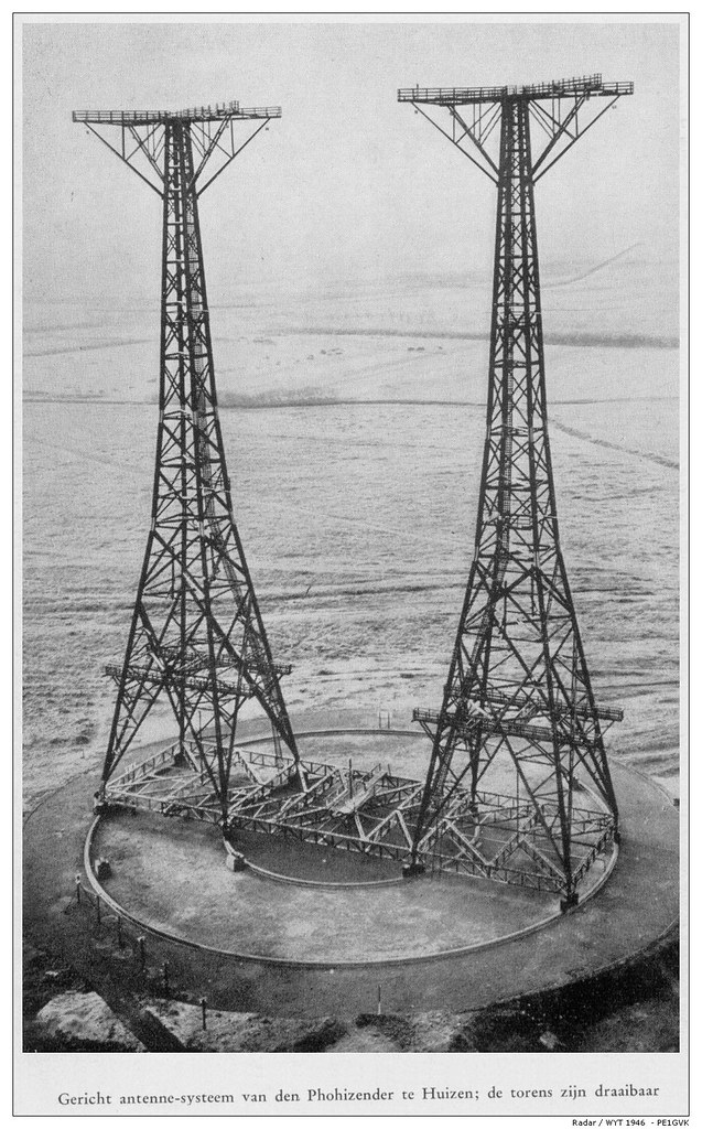
Gericht antenne-systeem van der Phohizender te Huizen; de torens zijn draaibaar

The rotating antenna masts. Installed in 1937. The complex structure was unique in the world. It was capable of optimising radiation power to the desired target area. It consisted of two 60 metre high towers. In order to maintain minimum absorption the towers were built of wood. The platforms in the summit served as suspension for the antennas. In the direction of the beam, the radiation is a total of 24 times stronger than a simple dipole.

Source

Tuesday, September 20, 2011

Exploring Abandoned Teufelsberg

Just outside of Berlin stands the Teufelsberg - or Devil's Mountain-an artificial hill made of millions of pounds of rubble from wartime Berlin (at the very bottom lies Albert Speer's unfinished technical college). After the war ended, the National Security Agency (NSA)built a series of buildings and geodesic radar domes atop the 280-foot high hill, in order to monitor Soviet activity. It was decommissioned after the Berlin Wall fell, though the ruins still stand today.

Exploring Abandoned Teufelsberg


Wednesday, March 24, 2010

Antenna Effects in Depolarization Measurements

Blanchard, A.J.; Jean, Buford Randall, "Antenna Effects in Depolarization Measurements," IEEE Transactions on Geoscience and Remote Sensing, vol.GE-21, no.1, pp.113,117, Jan. 1983, doi: 10.1109/TGRS.1983.350537

Abstract: The depolarization of electromagnetic energy scattered from natural terrain has been of interest to experimenters and theoreticians for many years. However, the reported measurements have not agreed with theoreticaly predicted results. Boresight axial ratio has commonly been used as a figure of merit to describe the polarization isolation properties of the measurement system antennas. Since depolarization measurements from terrain involve extended targets which fill the full antenna beam, boresight axial ratio is often an inadequate measure of antenna polarization purity. This paper describes antenna isolation characteristics which impact the quality of the depolarized measurements. Representative calculations demonstrate the effects of nonideal antenna systems on the observed measurements. A criterion for antenna specification is given which will provide high-quality cross-polarized measurements.

Source

Thursday, September 25, 2008

Holographic Research to Enhance Aircraft Antennas

The US Air Force has funded researchers at HRL Laboratories in Malibu, California to work on innovative new holographic techniques to create antennas that do not detract from an aircrafts aerodynamics.

The team are working on holographic impedance surfaces that will make antennas completely flush with the surface of the aircraft while still maintaining or even enhancing current protruding antenna capabilities.

The team are building the surfaces out of metallic materials on a substrate.

Programme manager at the Air Force Office of Scientific Research, Dr Arje Nachman said that the technology offers several benefits.

"One attractive benefit offered by these interesting surfaces is that if the tail of an aircraft obstructs the beam of an antenna then the tail can be covered by a suitably crafted impedance surface in such a way that the antenna beam flows around the tail as if the tail weren't there," Nachman said.

The HRL team is now trying to extend the capabilities of the electromagnetic impedance and experiment with practical implementations of it.

The researchers plan to create new kinds of unit cells and are also seeking new mapping techniques that allow those cells to be positioned over complex objects.

By Daniel Garrun.

Wednesday, April 25, 2007

Haystack Observatory

The MIT Haystack observatory is about an hour outside of Boston. The dish antenna inside the radome (a golf ball like structure but it only repeats about 3 times) measures 37 meters in diameter (over 100 feet). Scientists operate the giant antenna (dish) in the building under the radome. Many experients take place here, for example: "one of the more impressive ideas presented by the speakers involved masers, which glow inside large molecular clouds. Their use is a very clever way to map movement of the gases in distant nebula and galaxies."